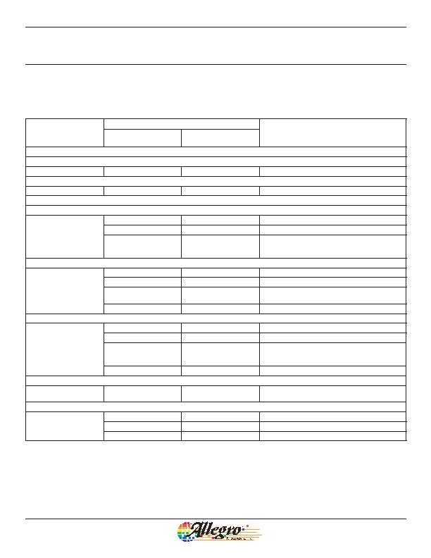
Programming Logic
Register Selection Key
Bitfield Address
Description
Binary Format
(MSB ?/SPAN> LSB)
Decimal Equivalent
Code
Mode Register Selection
Blow / Lock
1
01
1
Blow or Lock
Try
2
10
2
Try
Parameter Register Selection
Sensitivity / Coarse D
(Q)
1
000000000
0
Initial value; D
(Q)
= D
(Q)PRE
,
Sens = Sens
PRE
011111111
255
Maximum gain value in range
100000000
256
Enable Coarse D
(Q)
bit; switch from bidirectional
programming to unidirectional programming,
D
(Q)
= D
(Q)UNIinit
Fine D
(Q)
(B = 0 gauss)
2
000000000
0
Initial value
011111111
255
Maximum D
(Q)
in range
100000000
256
Switch from programming increasing D
(Q)
to
programming decreasing D
(Q)
111111111
511
Minimum D
(Q)
in range
PWM Frequency /Coarse PWM Frequency
3
00000
0
Initial value; f
PWM
= f
PWMPRE
01111
15
Minimum f
PWM
in f
PWM(fast)
range
10000
16
Enable Coarse f
PWM
bit; switch from f
PWM(fast)
programming to f
PWM(slow)
programming,
f
PWM
= f
PWM(slow)init
11111
63
Minimum f
PWM
in f
PWM(slow)
range
Null
4
Recommended to be selected before and during test
measurements performed in Try mode
Calibration Test Mode / Lock All
5
0000000000
0
Initial value
0000010000
16
Enable 50% duty cycle Calibration Test Mode bit
1000000000
512
LOCK bit; lock all device registers
High Precision 2-Wire Linear Hall Effect Sensor IC
with Pulse Width Modulated Output
A1354
18
Allegro MicroSystems, Inc.
115 Northeast Cutoff
Worcester, Massachusetts 01615-0036 U.S.A.
1.508.853.5000; www.allegromicro.com
发布紧急采购,3分钟左右您将得到回复。
相关PDF资料
A1356LKB-T
IC SENSOR HALL EFFECT 3 SIP
A1361LKTTN-T
IC HALL EFFECT SENSOR LN 4-SIP
A1374EKB-T
IC SENSOR HALL EFFECT PREC 3-SIP
A1422LK
IC SENSOR HALL EFFECT AC 4-SIP
A1425LK
IC SENSOR HALL EFFECT AC 4-SIP
A1645LK-I2
IC SENSOR HALL EFFECT AC 4-SIP
A3230LUA-T
IC SW HALL EFFECT CHOPPER 3-SIP
A3241LUA-T
IC SWITCH HALL EFFECT 3-SIP
相关代理商/技术参数
A1354KKTTN-T
功能描述:IC HALL EFFECT SENSOR 2WIRE 4SIP RoHS:是 类别:传感器,转换器 >> 磁性 - 霍尔效应,数字式开关,线性,罗盘 (IC) 系列:- 标准包装:1 系列:- 传感范围:20mT ~ 80mT 类型:旋转 电源电压:4.5 V ~ 5.5 V 电流 - 电源:15mA 电流 - 输出(最大):- 输出类型:数字式,PWM,8.5 位串行 特点:可编程 工作温度:-40°C ~ 150°C 封装/外壳:20-SSOP(0.209",5.30mm 宽) 供应商设备封装:20-SSOP 包装:Digi-Reel® 其它名称:AS5132-HSST-500DKR
A1354P1-2
制造商:APEM 功能描述:
A1354P1-6
功能描述:SWITCH HARDWARE RoHS:是 类别:开关 >> 配件 系列:- 标准包装:100 系列:- 其它名称:886.0007886.0007-ND
A1354P2-4
制造商:APEM 功能描述:
A1354P2-5
功能描述:SWITCH HARDWARE RoHS:是 类别:开关 >> 配件 系列:- 标准包装:100 系列:- 其它名称:886.0007886.0007-ND
A1355P1-2
制造商:APEM 功能描述:
A1355P1-3
制造商:APEM 功能描述:
A1355P1-8
制造商:APEM 功能描述: